

Introduction
GRMS is the root mean square acceleration value expressed in units of g. In vibration engineering, however, it may refer to the overall acceleration of a random vibration environment, or it may appear in vibration motor specifications to indicate output measured under specific test conditions. The two cannot be directly compared based on units alone.
This article explains what GRMS means, its units, and how it is calculated. It also explains how engineers should interpret Grms data in micro vibration motor specifications and what conditions need to be verified when comparing test results. As a micro vibration motor manufacturer, LEADER lists vibration parameters for corresponding models in its product documentation; these data should be understood in conjunction with the specific model and test conditions.
What Is GRMS?
GRMS is the root mean square value of an acceleration signal, typically expressed as gRMS. In random vibration testing, it summarizes the overall RMS acceleration within a specified frequency range. In vibration motor specifications, Grms may also represent the acceleration output measured under specific test conditions.
When you see GRMS or Grms, the first step is to confirm what is being measured: does the data describe the random vibration environment the device is subjected to, or the vibration output generated by the motor itself? Although these two types of data use similar units, their measurement purposes and test conditions differ, and they cannot be directly compared based on numerical values alone.
What Is the Full Name and Unit of GRMS?
GRMS generally refers to RMS (Root Mean Square) acceleration expressed in units of g. RMS is a calculation method for processing varying signals; g is the unit of gravitational acceleration, and 1g is approximately equal to 9.81m/s29.81m/s2.
In engineering documentation, it is also commonly written as gRMS, Grms, or GRMS. Regardless of the notation used, the context should be checked to confirm that the metric represents acceleration, not vibration displacement, velocity, or motor speed. For motor specifications, the test method and conditions for the corresponding model should also be reviewed.
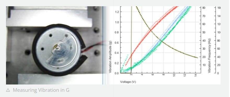
How Is GRMS Calculated?
GRMS can be calculated from time-domain acceleration data or from a frequency-domain PSD curve. The time-domain method is based on a series of acceleration samples; the PSD method integrates the acceleration spectral density over a specified frequency range. Both methods require a clear definition of the data range and test conditions.
Calculating from Time-Domain Acceleration Data
For time-domain sampled data, RMS acceleration equals the square root of the average of all squared acceleration samples:
where a1a1 through anan are acceleration samples and nˉnˉ is the number of samples. If the signal contains sensor offset or DC components not generated by vibration, corrections should be made before calculation according to the measurement method. If the data is expressed in m/s2m/s2, it can be converted to gg by dividing by approximately 9.81.
Calculating from a PSD Curve
Random vibration testing commonly uses acceleration Power Spectral Density (PSD) to describe the vibration distribution across different frequencies. PSD units are typically g2/Hzg2/Hz. By integrating the PSD over a specified frequency range and then taking the square root of the integrated area, GRMS is obtained.
GRMS == √(Integrated Area of PSD over the Specified Frequency Range)
The unit of the PSD integrated area is g2g2, and taking the square root yields gRMS. For curves composed of multiple frequency segments and different slopes, the area of each segment should be calculated separately using the appropriate method, summed, and then the square root taken. Actual calculations should follow the applicable test specification or analysis software method. The frequency range also affects the final result, so when comparing two GRMS values, confirm that the same frequency range and PSD conditions were used.
What Is the Difference Between GRMS, G Peak, and Peak-to-Peak?
GRMS, G Peak, and Peak-to-Peak describe different characteristics of a vibration signal and generally cannot be directly interchanged. GRMS represents the root mean square acceleration of a signal segment; G Peak represents the maximum instantaneous acceleration during measurement; Peak-to-Peak represents the difference between the maximum and minimum values.
| Metric | What It Represents | What to Note When Using |
| GRMS / gRMS | Root mean square level of an acceleration signal segment | Measurement object, frequency range, and test conditions must be specified |
| G Peak | Maximum instantaneous acceleration during measurement | Affected by signal peak characteristics and recording duration |
| Peak-to-Peak | Difference between maximum and minimum values | Cannot be universally derived from RMS values |
For an ideal sine wave, there is a fixed relationship between RMS and peak value; however, the peak value of a random vibration signal depends on the signal distribution, crest factor, and recording duration, and the sine wave formula cannot be directly applied. Engineers should not estimate the peak or peak-to-peak value of random vibration from a single GRMS value alone.
What Does Grms Mean in Vibration Motor Datasheets?
In micro vibration motor datasheets, Grms typically represents the acceleration output measured under specific test methods and conditions. It is not a fixed "haptic strength" that remains constant regardless of test setup, and it should be interpreted together with the model, drive conditions, and measurement method.
For example, LEADER's FPCB-0820 product documentation lists a vibration value of 0.6 Grms. This value should be understood in conjunction with the corresponding model and datasheet; if used for engineering comparison, it is also necessary to confirm whether the actual measurement conditions are consistent.
Why Might the Same Motor Measure Different Grms Values?
Differences in mounting, fixture, load, measurement axis, and drive conditions can all cause the same motor to measure different Grms values. Fixture stiffness and damping affect vibration transmission; different accelerometer positions or orientations may also record different responses. Drive voltage, LRA drive frequency, clamping pressure, and housing structure can also change measurement results.
To improve test repeatability, it is recommended to record the motor model, drive conditions, mounting method, load, accelerometer position, measurement axis, frequency range, and test duration for each measurement. When comparing data, these conditions should be kept as consistent as possible, and any conditions that cannot be standardized should be clearly documented.
What Can GRMS Tell You, and What Can It Not Tell You on Its Own?
GRMS can summarize the overall RMS acceleration level under specific measurement conditions, but a single value cannot fully describe a vibration signal. For random vibration environments, GRMS alone cannot show which frequencies the vibration energy is concentrated in; engineering evaluation may also require reviewing the PSD curve, specified frequency range, and test duration.
A single GRMS value also cannot directly indicate:
The maximum instantaneous peak value in random vibration;
The contribution of different frequency bands to the overall response;
Where the maximum vibration occurs in the product structure;
Whether the motor's service life or reliability meets requirements;
Whether the user's final perceived vibration is stronger or more comfortable.
If evaluating the random vibration that equipment is subjected to, the frequency spectrum and test duration should be considered together. If evaluating the motor's own output, the model, drive, fixture, load, and measurement axis should be considered together. In neither case should a complete judgment be made based on a single GRMS number alone.
What Information Should Be Provided to the Manufacturer When Evaluating Micro Vibration Motors?
When evaluating motor specifications or samples, the engineering team should specify the measurement object, target metrics, and actual usage conditions. This information helps LEADER determine whether the project is concerned with the equipment's environmental vibration or the motor output, and to confirm the appropriate specifications or sample evaluation conditions.
Recommended preparation:
Product type and target application;
Whether the evaluation concerns environmental random vibration or motor output;
Target Grms, G Peak, or other vibration metrics;
Applicable frequency range and related test requirements;
Motor mounting space, orientation, fixing method, and product structure;
Available voltage, drive circuit, and LRA drive frequency (if applicable);
Test fixture, load, and accelerometer position (if a test setup already exists);
Motor model, sample quantity, and project stage to be evaluated.
If the target values have not yet been determined, you may first provide the product structure, drive conditions, existing test reports, or reference prototypes. LEADER can further confirm available parameters and sample evaluation requirements based on the specific model documentation.
Explore Leader's small vibration motor solutions or custom linear motor options when evaluating motors for compact electronic devices.
GRMS generally refers to the root mean square acceleration value expressed in units of g. It describes the RMS level of an acceleration signal, and its specific meaning should be determined in conjunction with the measurement object and test conditions.
GRMS is typically expressed as gRMS for acceleration. 1g is approximately equal to 9.81 m/s29.81 m/s2. In engineering documentation, it may also be written as gRMS, Grms, or GRMS.
Is GRMS the same as G Peak? No. GRMS is the root mean square acceleration value, while G Peak is the maximum instantaneous acceleration during measurement. The relationship between the two depends on the signal waveform; random vibration cannot be directly converted using the ideal sine wave formula.
Not recommended. It should be confirmed whether the test fixture, load, mounting orientation, drive conditions, and measurement method are the same for both motors. If the test conditions differ, comparing Grms values alone may lead to incorrect conclusions.
Can the Grms in a motor datasheet represent the vibration intensity actually felt by the user? It cannot represent this on its own. The Grms in a datasheet is a measured value under a specific test setup; actual vibration transmission is also affected by the housing, mounting method, device mass, contact location, and drive conditions, and should be verified in the target structure.
Conclusion
GRMS is a root mean square metric for acceleration, but in different contexts, it may describe a random vibration environment or represent the output of a vibration motor measured under specific conditions. Before interpreting or comparing data, the measurement object, units, frequency range, and test conditions should first be confirmed.
Consult Your Leader Experts
We help you avoid the pitfalls to deliver the quality and value your micro brushless motor need, on-time and on budget.
Post time: Jan-16-2025


