

For engineers and hardware developers, integrating a coin vibration motor into a printed circuit board (PCB) design requires careful consideration of multiple technical aspects. Whether you're working on a smartphone, a wearable device, or an industrial control panel, a well-integrated coin vibration motor (also known as a pancake vibration motor or flat vibration motor) can enhance user experience by providing effective haptic feedback. This comprehensive guide covers all the essential technical details and steps to ensure a seamless integration process.
1. Understanding the Technical Specifications of Coin Vibration Motors
1.1 Voltage and Current Requirements
Voltage: Most commonly, coin vibration motors operate at a low voltage. Standard models often work with 3V, which is ideal for battery-powered devices like smartwatches and wireless earbuds. However, depending on the application, motors can be designed to operate at 1.8V, 3.7V, or 4V. For example, in some industrial control systems where a stronger vibration is required, a 4V coin type vibration motor might be used. It's crucial to match the motor's rated voltage with the power supply on your PCB to avoid underperformance or damage.
Current: The current consumption of coin vibration motors typically ranges from a few milliamps to tens of milliamps. A small 6mm coin vibration motor might draw around 40-60mA at 3V. Exceeding the rated current can lead to overheating and reduced lifespan of the motor. Make sure your PCB's power management circuit can supply the required current without voltage drops.
1.2 Lead Length and Connection Type
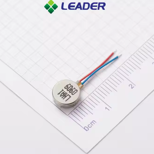
Lead Length: The length of the leads connecting the coin vibration motor to the PCB is an important factor. Shorter leads (e.g., 10 - 20mm) are suitable for applications where space is extremely limited, such as in small wearables. Longer leads (up to 50mm or more) can provide flexibility in positioning the motor away from the main PCB, which might be necessary in devices with complex internal layouts. When soldering the leads to the PCB, ensure that the length allows for some slack to avoid mechanical stress on the solder joints during device operation.
Connection Type:
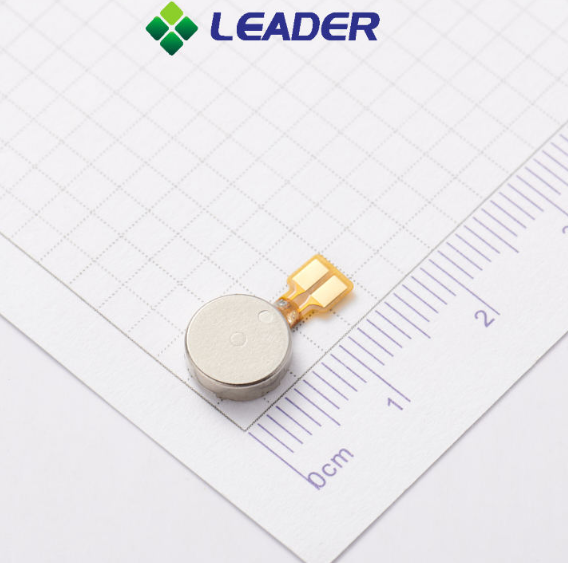
FPCB (Flexible Printed Circuit Board): FPCB connection offers excellent flexibility in PCB design. The flexible nature of the FPCB allows for easy routing in tight spaces and around complex internal structures of devices. It can be bent, folded, or twisted to position the coin vibration motor precisely where needed. This type of connection is particularly popular in slim and compact devices like smartphones and smartwatches, where minimizing the overall thickness and maximizing space utilization are crucial. When using an FPCB connection, the motor is typically attached to one end of the FPCB, and the other end is then soldered or connected to the main PCB. This connection method also helps in reducing mechanical stress on the motor during device assembly and operation.
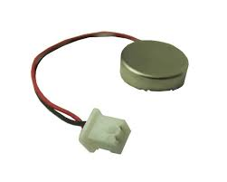
Connector - Style: Connector-based connections provide a more modular and detachable solution. With a connector - style connection, the coin vibration motor comes with a pre - attached connector, and a corresponding socket is mounted on the PCB. This makes it easier to install, remove, or replace the motor during the manufacturing process or for maintenance purposes. It's a great option for devices where quick assembly and disassembly are required, or when you want to be able to swap out motors with different specifications easily. Additionally, connector - style connections can offer better electrical contact reliability and are less prone to soldering - related issues compared to some other connection methods.
3. Electrical Integration and Circuit Design
3.1 Power Supply Circuit
Filtering and Regulation: Since coin vibration motors can cause electrical noise during operation, it's essential to include filtering and regulation in the power supply circuit. A simple RC (resistor - capacitor) filter can be added between the power source and the motor to reduce voltage spikes and noise. Additionally, if the power supply voltage is higher than the motor's rated voltage, a voltage regulator circuit (such as an LDO - Low Dropout regulator) should be used to step down the voltage.
Switching Control: To control the operation of the coin vibration motor, a switching circuit is usually required. This can be implemented using transistors (e.g., N - channel MOSFETs) or dedicated motor driver ICs. The switching circuit allows you to turn the motor on and off as needed, for example, to generate vibration alerts or feedback.
3.2 Signal Control
Pulse - Width Modulation (PWM): PWM is a common technique used to control the vibration intensity of coin vibration motors. By varying the duty cycle of the PWM signal, you can adjust the average voltage applied to the motor, which in turn controls the vibration strength. For example, a 50% duty cycle will result in a medium - strength vibration, while a 100% duty cycle will produce the maximum vibration intensity.
Logic Control: Connect the control signal from your microcontroller or other logic circuit to the switching circuit of the motor. Make sure to use appropriate level - shifting circuits if there is a voltage mismatch between the logic circuit and the motor driver.
4. LEADER's Technical Support and Prototype Services
At LEADER, we understand the challenges engineers face when integrating coin vibration motors into their PCB designs. That's why we offer comprehensive technical support:
Pre-Design Consultation: Our team of experienced engineers can help you select the right coin vibration motor for your specific application. We'll consider factors such as voltage requirements, vibration intensity, size constraints, and mounting options to ensure the best fit for your PCB design.
Technical Documentation: Every coin vibration motor we supply comes with detailed datasheets that include electrical specifications, mechanical dimensions, and recommended operating conditions. We also provide reference circuit designs for power supply and signal control to assist you in your PCB layout.
Prototype Services: Need to test a coin vibration motor in your PCB design before mass production? We offer rapid prototyping services. Our team can produce custom-made motors according to your specific requirements, including unique dimensions, voltage ratings, and connection types. We'll also provide samples for you to test in your PCB prototype, ensuring that the integration meets your expectation.

FAQ: Answering Your Technical Questions
Q1: Can I use a coin vibration motor with a higher voltage than its rated value for a short time to get stronger vibration?
A: It's not recommended. Operating a coin vibration motor above its rated voltage for an extended period can cause overheating, damage to the motor windings, and significantly reduce its lifespan. If you need a stronger vibration, it's better to choose a motor with a higher rated vibration intensity or use a PWM signal to control the existing motor.
Q2: How do I minimize the noise generated by the coin vibration motor on my PCB?
A: You can use several techniques. First, add a proper RC filter in the power supply circuit to suppress electrical noise. Second, ensure proper grounding of the motor and the PCB to reduce electromagnetic interference. Third, use shielding materials around the motor if necessary, especially in applications where noise sensitivity is high.
Q3: What should I do if the coin vibration motor doesn't vibrate as expected after integration?
A: First, check the power supply voltage and current to ensure they match the motor's requirements. Then, verify the soldering connections of the leads to the PCB to make sure there are no open or short circuits. Also, check the control signal to the motor to ensure it's functioning correctly. If the problem persists, contact our technical support team at LEADER for assistance.
Q4: Can I change the vibration frequency of a coin vibration motor?
A: The vibration frequency of a coin vibration motor is mainly determined by its mechanical design, such as the shape and weight of the eccentric mass. However, you can control the perceived vibration pattern by using PWM signals to turn the motor on and off at different intervals, which can create the effect of different vibration frequencies.
Conclusion
Integrating a coin vibration motor into your PCB design requires careful attention to technical specifications, mounting methods, and electrical integration. By following the guidelines in this article and leveraging the technical support and prototype services offered by LEADER, you can ensure a successful integration. Whether you're working on a consumer electronics product or an industrial device, a well - integrated coin type vibration motor can add valuable haptic feedback functionality.
Need coin vibration motors for your next project? Contact our factory today for a free quote. Our team of experts is ready to assist you with all your coin vibration motor needs, from selection to integration.
Consult Your Leader Experts
We help you avoid the pitfalls to deliver the quality and value your micro brushless motor need, on-time and on budget.
Post time: Jul-01-2025


