

A vibration motor may be a small component, but designing its driving circuit correctly is essential for achieving reliable and consistent vibration performance.
Whether you are developing a wearable device, smartphone, gaming controller, smart home product, or medical device, the motor circuit determines how efficiently the actuator operates and how accurately it responds to control signals.
A well-designed vibration motor circuit should provide sufficient driving current, stable power delivery, accurate vibration control, and reliable protection.
In this guide, we will explain how to design a vibration motor driver circuit, select the right components, build a basic circuit, and test its performance.
1. Understanding the Basics of a Vibration Motor Circuit
A vibration motor circuit typically consists of four main elements:
- Power Supply: Provides the voltage and current required by the motor.
- Motor Driver: Controls the electrical power delivered to the motor.
- Controller: Sends control signals to determine when and how the motor operates.
- Vibration Motor: Converts electrical energy into mechanical vibration.
The actual circuit depends on the motor type. ERM and LRA motors have different operating principles and therefore require different driving methods.
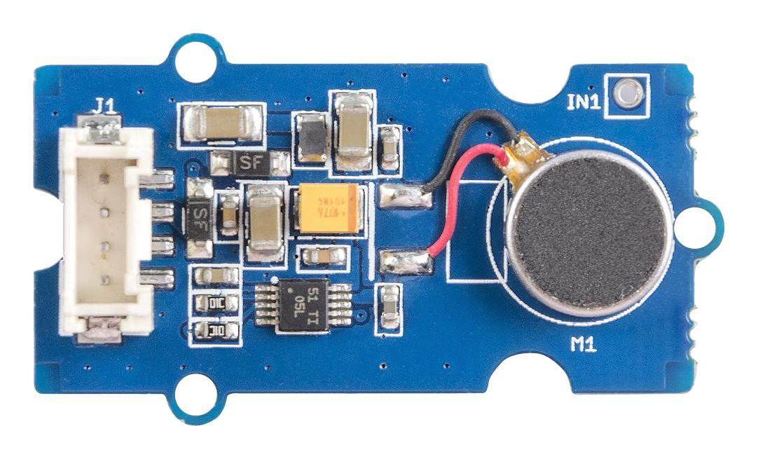
ERM vs. LRA: Different Driving Requirements
| Feature | ERM Motor | LRA Motor |
|---|---|---|
| Operating principle | Rotating eccentric mass | Linear resonant movement |
| Driving signal | DC voltage, commonly PWM-controlled | AC or alternating drive waveform |
| Speed control | Adjust voltage or PWM duty cycle | Adjust drive amplitude and waveform |
| Frequency control | Mainly determined by motor speed | Requires resonance-frequency consideration |
| Typical driver | MOSFET or motor driver IC | Dedicated haptic driver IC |
| Common applications | Wearables, toys, small electronics | Smartphones, controllers, precision haptics |
Important: An ERM motor can often be driven using a relatively simple switching circuit. An LRA generally needs a dedicated driver capable of generating and controlling an alternating waveform. Some advanced drivers also provide resonance tracking and braking functions.
2. How to Design a Basic Vibration Motor Driver Circuit
For a basic ERM vibration motor, a low-side MOSFET switching circuit is a practical starting point. It allows a microcontroller to turn the motor on and off without supplying the motor current directly through a GPIO pin.
Basic ERM Motor Circuit
The main components include:
- N-channel MOSFET: Acts as an electronic switch to control motor power.
- Flyback Diode: Helps suppress the inductive voltage spike generated when the motor is switched off.
- Gate Resistor: Limits the transient current flowing into the MOSFET gate.
- Pull-down Resistor: Keeps the MOSFET switched off when the control signal is floating.
- Decoupling Capacitor: Helps reduce supply voltage fluctuations caused by motor startup and switching.
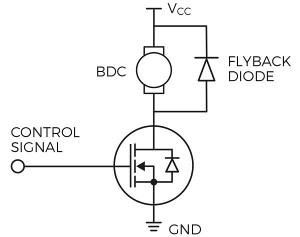
How does it work?
When the microcontroller outputs a HIGH signal, the MOSFET turns on and allows current to flow through the vibration motor. The motor starts rotating and generates vibration.
When the control signal goes LOW, the MOSFET switches off and interrupts the motor current. The flyback diode provides a path for the inductive current to decay safely.
This design is relatively simple and cost-effective, making it suitable for basic vibration functions in toys, small electronic devices, and other products using ERM motors.
Design note: Select the MOSFET based on the motor's startup or stall current, not just its normal operating current. Also, verify that its gate voltage is compatible with the microcontroller's output voltage.
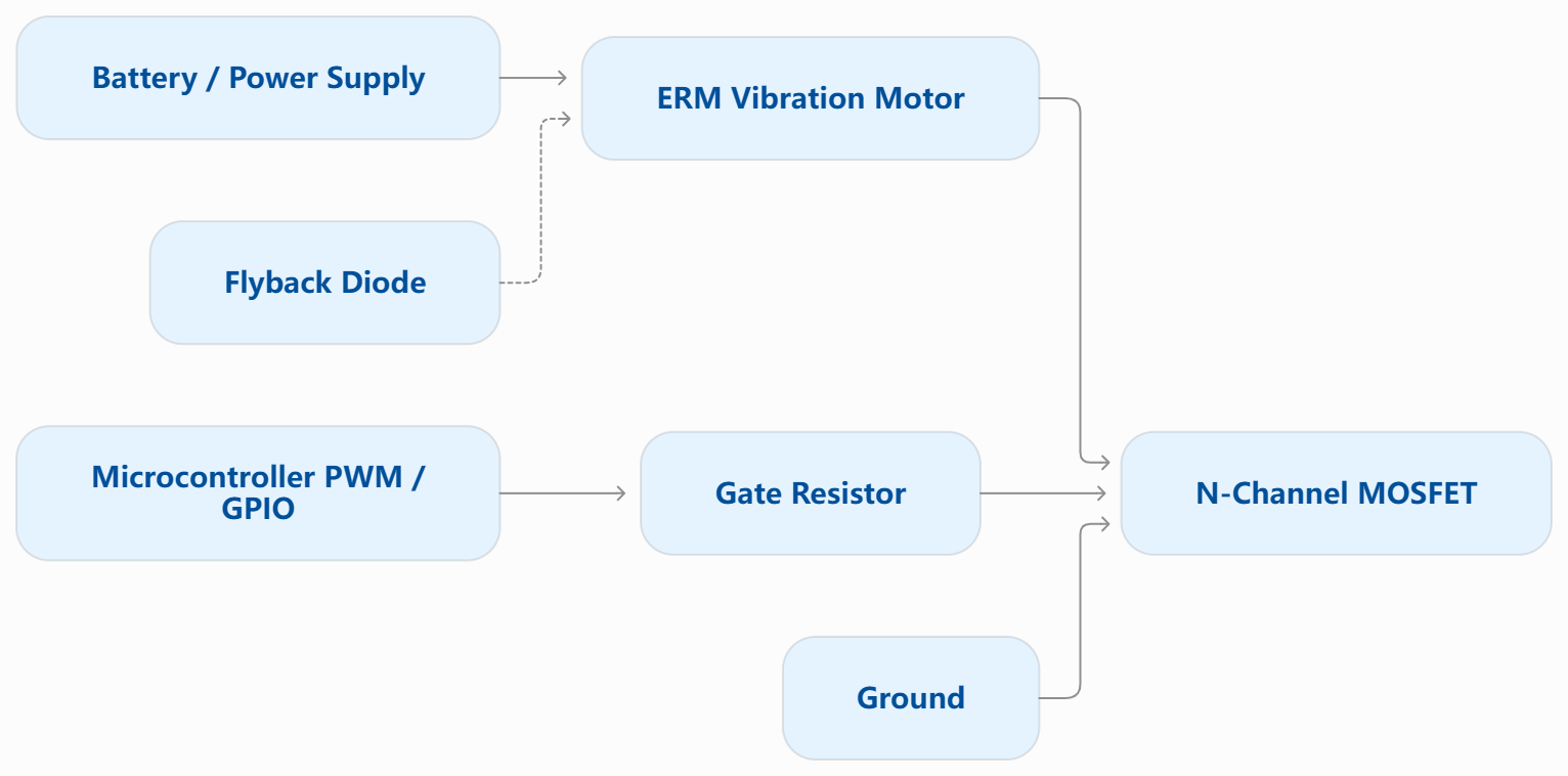
Basic Circuit Structure
The following diagram shows the general signal and power flow:
3. Choosing the Right Vibration Motor Driver IC
For more advanced products, using a dedicated motor driver IC is often a better solution than building a discrete circuit from individual components.
A dedicated driver can provide more accurate control, improve vibration consistency, and simplify circuit development.
| Driver Solution | Motor Type | Main Advantages | Suitable Applications |
|---|---|---|---|
| MOSFET switching circuit | ERM | Simple, low cost | Toys, basic electronics |
| H-bridge driver | ERM / compatible actuators | Bidirectional drive capability | Advanced motor control |
| Dedicated haptic driver | ERM / LRA, depending on IC | Waveform control, braking, advanced feedback | Smartphones, wearables |
| Programmable haptic driver | ERM / LRA, depending on IC | Flexible vibration effects | Gaming controllers, smart devices |
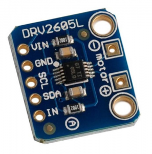
Example: TI DRV2605L Haptic Driver
This is a dedicated haptic driver designed for both ERM and LRA actuators. It supports I²C control, PWM input, automatic overdrive and braking, and LRA resonance tracking.
View official product information and datasheet
For projects that require precise haptic feedback, a dedicated driver can reduce the amount of custom control circuitry and software development.
For example, LRA applications benefit from resonance tracking because the optimal driving frequency can shift due to temperature, mechanical loading, and other operating conditions.
4. How to Control Vibration Motor Speed and Strength with PWM
PWM (Pulse Width Modulation) is one of the most common methods for controlling vibration motor output.
Instead of continuously changing the supply voltage, PWM rapidly switches the motor drive signal between ON and OFF states. By adjusting the duty cycle, the average power delivered to the motor can be controlled.
PWM Duty Cycle and Vibration Output
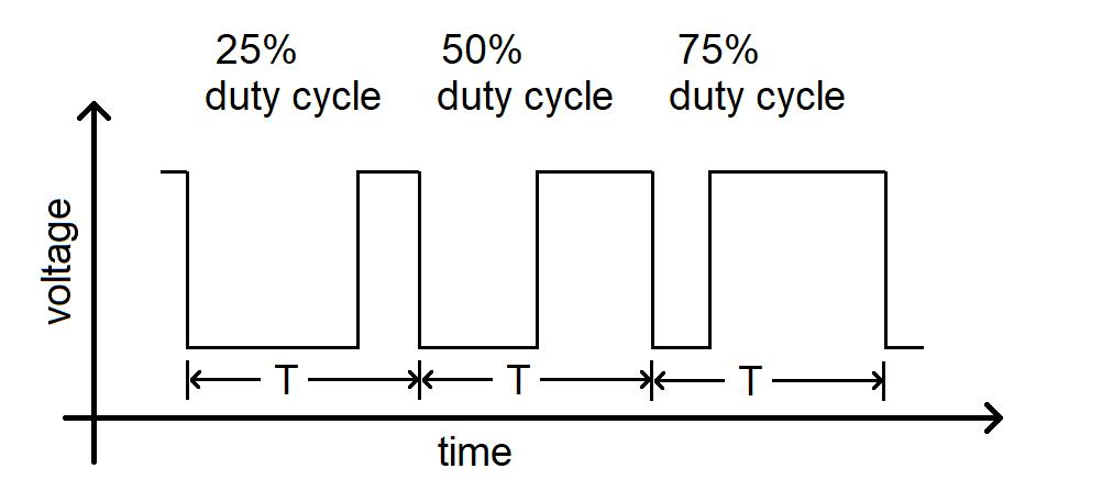
Why is PWM important?
PWM allows engineers to create different vibration intensities without requiring a separate power supply for every operating level.
For example, a wearable device may use gentle vibration for notifications and stronger vibration for alarms.
However, PWM duty cycle does not translate directly into the same percentage of perceived vibration strength. Actual performance depends on motor characteristics, drive frequency, load, mounting structure, and driver design.
For LRA motors, engineers must also consider resonance frequency and waveform requirements. Simply changing the PWM duty cycle of a basic DC switching circuit is not an appropriate substitute for a dedicated LRA drive signal.
5. How to Build and Test a Vibration Motor Circuit
After selecting the motor and driver, the next step is to build a prototype and verify its electrical and mechanical performance.
A circuit that works during a short bench test may still experience problems during continuous operation or inside the final product enclosure.
Step 1: Check the Motor Specifications
Before connecting the motor, confirm the following parameters:
- Rated operating voltage
- Operating current and startup current
- Maximum allowable voltage
- Motor dimensions and mounting requirements
- Recommended driving method
- Resonance frequency (for LRA motors)
These specifications help prevent overcurrent, insufficient vibration, and premature motor failure.
Step 2: Assemble the Circuit
Connect the motor, driver IC, power supply, and controller according to the circuit design.
Keep power traces sufficiently wide for the expected current. Place bypass capacitors close to the driver power pins, and avoid routing sensitive control signals alongside noisy switching paths where possible.
Step 3: Test the Electrical Performance
Use a multimeter and oscilloscope to check whether the circuit operates as expected.
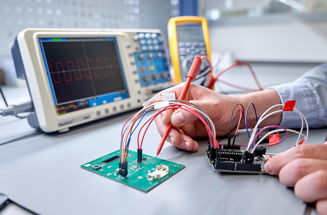
Important measurements include:
- Supply Voltage: Check whether the voltage remains stable when the motor starts.
- Operating Current: Measure the current under normal operating conditions.
- Startup Behavior: Observe whether the motor starts consistently.
- PWM Waveform: Verify the signal frequency and duty cycle.
- Driver Temperature: Check whether the driver or MOSFET overheats during operation.
For differential LRA outputs, use an appropriate differential measurement method rather than assuming either output terminal is ground.
Step 4: Evaluate Mechanical Vibration
Electrical measurements alone cannot fully describe vibration performance.
Use an accelerometer or vibration measurement instrument to evaluate the motor's actual output.
Pay attention to:
- Vibration acceleration and consistency
- Startup response time
- Braking and stopping behavior
- Noise and unwanted resonance
- Performance under different mounting conditions
The motor should also be tested inside the actual product enclosure because housing materials and mounting structures can significantly affect the perceived vibration.
Step 5: Perform Reliability Testing
For OEM projects, prototype testing should be followed by reliability evaluation.
Typical tests include repeated start-stop cycles, continuous operation, voltage variation, temperature testing, and vibration consistency checks.
These tests help identify problems before mass production.
6. Common Vibration Motor Circuit Design Problems
Even a properly selected motor can perform poorly if the driver circuit is not designed correctly.
| Common Problem | Possible Cause | Recommended Solution |
|---|---|---|
| Motor does not start | Insufficient voltage or current | Check supply capacity and startup current |
| Weak vibration | Incorrect PWM settings or poor mounting | Optimize drive parameters and mechanical installation |
| Unstable vibration | Power supply fluctuations | Improve decoupling and power layout |
| Excessive heating | Overcurrent or unsuitable driver | Check current ratings and operating conditions |
| Slow stopping | Motor inertia or insufficient braking | Evaluate active braking or driver options |
| Poor LRA performance | Incorrect driving frequency | Use an appropriate LRA driver and resonance tracking |
A key design consideration: Do not evaluate a vibration motor only by its nominal voltage. The interaction between the motor, driver, power supply, and mechanical structure determines the final vibration experience.
7. Vibration Motor Circuit Design Checklist for OEM Projects
When developing a new electronic product, engineers should evaluate more than just whether the motor can vibrate.
The following checklist can help reduce design problems before moving into mass production.
Circuit Design Checklist
For customized products, it is also important to confirm the motor dimensions, connector type, FPCB design, mounting position, and assembly requirements early in the development process.
Conclusion: Build a Better Vibration Motor Circuit
Designing a reliable vibration motor circuit requires the right combination of motor selection, driver design, power management, and performance testing.
For basic ERM applications, a MOSFET switching circuit may be sufficient. For advanced haptic applications using LRA motors, a dedicated driver with waveform control and resonance tracking can provide more precise and consistent performance.
Most importantly, the circuit should be evaluated together with the actual motor and final product structure. This helps ensure that the finished device delivers the expected vibration quality, reliability, and user experience.
Looking for a reliable vibration motor manufacturer?
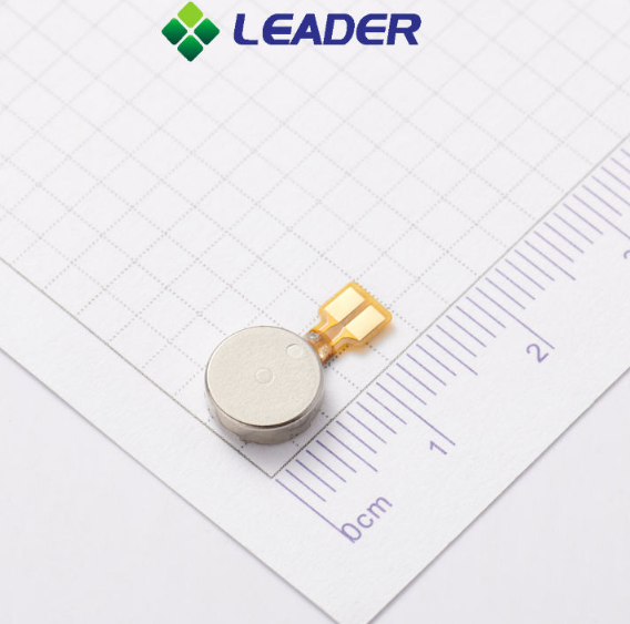
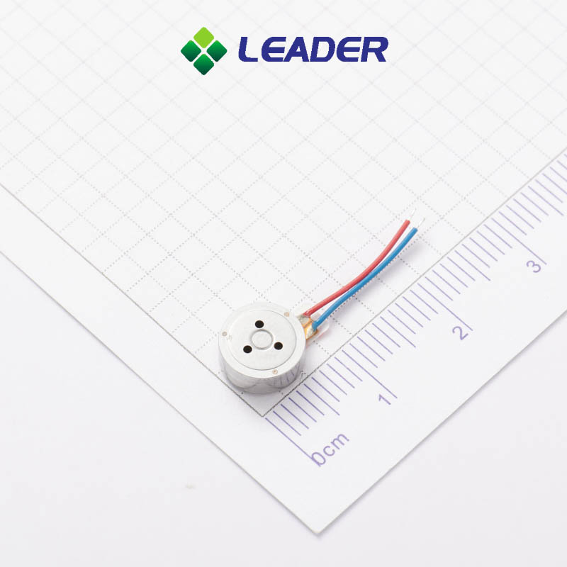
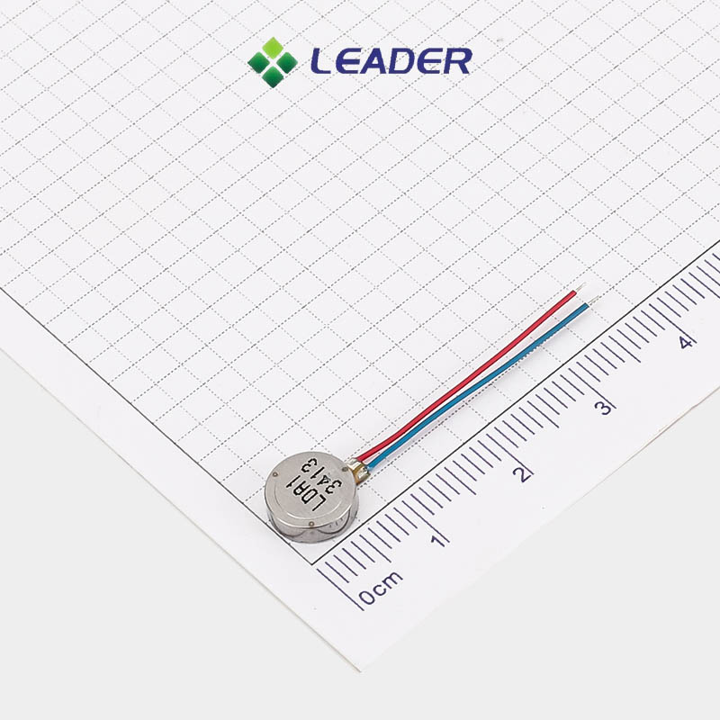
At LEADER, we provide customized micro vibration motor solutions for different product requirements, including:
- Bldc Vibration Motors for compact electronic devices.
- Custom Linear Motors for precision haptic feedback applications.
- Coin Vibration Motors for wearable and space-limited products.
Contact our team to discuss your motor specifications, circuit requirements, and OEM/ODM customization needs.
Generally, it is not recommended. Most microcontroller GPIO pins cannot supply the current required by a vibration motor. Use an appropriate MOSFET or motor driver circuit to control the motor safely.
No. ERM motors typically operate using DC power and can be controlled through a suitable switching circuit. LRA motors require an alternating drive waveform, usually generated by a dedicated haptic driver.
PWM control is commonly used for ERM motors. Adjusting the duty cycle changes the average power delivered to the motor. For LRA motors, the driver must also manage waveform amplitude and resonance requirements.
Possible reasons include insufficient supply voltage, inadequate driving current, incorrect PWM settings, unsuitable mounting, or an incompatible driver. For LRA motors, incorrect driving frequency is another important possibility.
Consider motor type, operating voltage, peak current, control interface, PWM capabilities, braking requirements, and whether resonance tracking is needed. The driver should always be compatible with the motor's electrical specifications.
Start with a compatible motor and driver, provide stable power, avoid exceeding rated operating conditions, and perform electrical, mechanical, and lifecycle testing under realistic application conditions.
Consult Your Leader Experts
We help you avoid the pitfalls to deliver the quality and value your micro brushless motor need, on-time and on budget.
Post time: Jan-11-2025


