
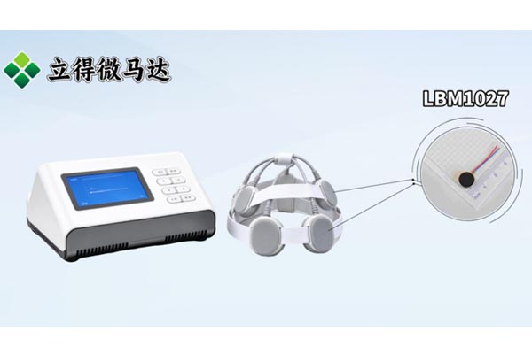
Transcranial magnetic stimulation (TMS) devices use pulsed magnetic fields to deliver non-invasive stimulation. For manufacturers developing a head-worn TMS device or treatment cap, a compact vibration motor may be evaluated as an optional tactile feature, depending on the device design and intended use.
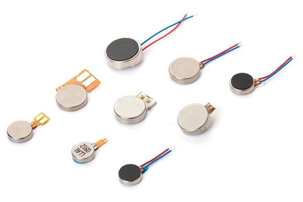
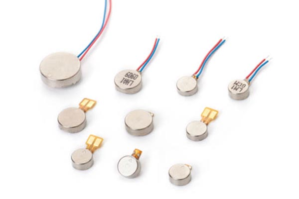
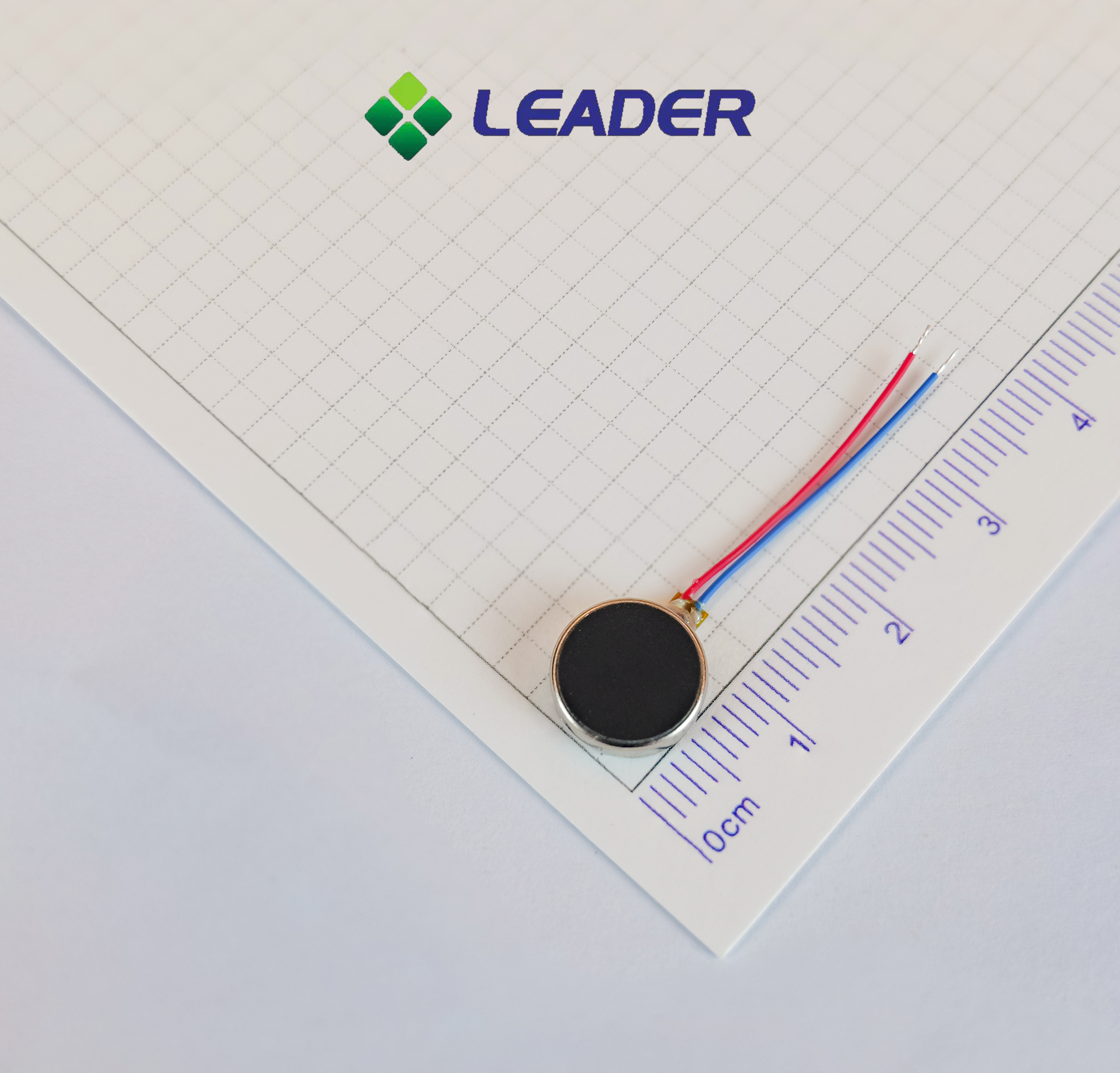
The LEADER LBM1027 is a φ10 × 2.7 mm brushless vibration motor for compact device designs. Project teams can assess its size, operating range, vibration output, drive conditions, and mounting method as part of the complete device evaluation.
Where a Vibration Motor May Fit in a TMS Device
A vibration motor may be considered for integration into a designated area of a head-worn device or treatment cap when the product design calls for an additional tactile output. Its position and mounting method depend on the available space, cap or housing structure, contact materials, and the device’s operating requirements.
The motor generates vibration; the device’s control board and drive circuit determine when and how it operates. The motor’s behavior in the finished product should be evaluated after installation, because the housing, mounting structure, and contact surface can affect the vibration users perceive.
What Device Teams Should Evaluate Before Integration
Before selecting a motor for a TMS device project, engineering teams should review the motor together with the complete device design. These checks help determine whether the component’s output and operating conditions suit the intended product.
Available Space and Mounting
Check the space available in the cap or housing, including the motor’s thickness, wiring or connection method, and any mounting features. Confirm that the selected position works with the device’s structure and intended contact area.
Vibration Output in the Finished Device
Vibration measured on a test fixture may differ from the sensation produced after the motor is installed. Evaluate the motor in the actual mounting structure and under representative operating conditions before setting output expectations.
Drive Conditions and Operating Pattern
Confirm the supply voltage, current availability, drive circuit, and intended on/off pattern. If the device uses multiple motors, test the complete arrangement to assess output consistency under the selected control method.
Noise and User Interaction
Measure operating noise after installation, since the cap, housing, and mounting method may affect sound. Evaluate the complete device in its intended operating environment and according to the device manufacturer’s user requirements.
System-Level Compatibility and Safety
The TMS device manufacturer should assess the motor and its drive circuit as part of the complete system, including electromagnetic compatibility, electrical safety, and any applicable regulatory requirements. Component specifications alone do not establish the compliance of the finished device.
Why Evaluate the LEADER LBM1027 Brushless Vibration Motor?
The LBM1027 combines a compact form factor with brushless motor construction. It can be considered when a project requires a small vibration motor and the engineering team needs to evaluate its output and operating conditions within a head-worn device design.
Compact φ10 × 2.7 mm Form Factor
With a diameter of 10 mm and thickness of 2.7 mm, the LBM1027 can be assessed for designs with limited installation space. Final fit depends on the available cavity, mounting method, and surrounding components.
Brushless Motor Construction
The LBM1027 uses a brushless architecture. Motor selection should take the intended operating pattern, drive requirements, acoustic performance, and required service life into account; these characteristics should be verified in the finished device.
Defined Electrical Operating Range
The motor’s specified operating range is 2.5–3.8V DC, with a rated voltage of 3.0V DC. Engineering teams should confirm that the power supply and drive circuit remain within the motor’s specified conditions during operation.
Vibration Output for Project Evaluation
The LBM1027 has a minimum vibration force of 2.0G Peak when measured with a 100g testing jig. This value is a component test result; the output perceived in a finished TMS device will depend on the mounting structure and materials.
Specified Cycle Life Test
The motor is specified for 500,000 cycles under the test condition of 2 seconds on and 1 second off per cycle. The project team should compare this test condition with the device’s planned operating pattern and validation requirements.
LEADER LBM1027 Specifications
The following specifications are provided for initial component evaluation. Confirm the final motor configuration and test requirements with LEADER for your project.
| Model | LBM1027 |
| Operating Voltage(V) | 2.5~3.8V DC |
| Rated Voltage(V) | 3.0V DC |
| Rated Current(mA) | 80mA Max |
| Rated Speed(RPM) | 13500±3500 rpm |
| Vibration Force(G) | 2.0 G min (PEAK)Testing Jig(100g) |
| Lifetime | 500,000 Cycle (1 Cycle:2sec on/1sec off ) |
From Motor Evaluation to Device Validation
Selecting a vibration motor is one part of the device development process. The selected motor should be reviewed in the target structure and tested under representative operating conditions before design approval.
Share the Device Requirements
Provide the available installation space, power supply conditions, desired operating pattern, and project quantity. If possible, include a drawing or description of the cap or housing structure.
Review the Motor and Drive Conditions
The engineering teams can review the motor’s specifications and discuss the drive and connection requirements for the project.
Evaluate Samples in the Target Structure
Test the motor in the intended mounting position and device structure. Review vibration output, noise, electrical behavior, and interaction with the complete system.
Confirm the Production Configuration
After the sample evaluation, confirm the motor configuration and project requirements before moving to production planning.
Frequently Asked Questions
Can the LBM1027 be considered for a TMS therapy device?
The LBM1027 may be evaluated for a TMS device project that requires a compact vibration motor. The device manufacturer should verify its mechanical fit, electrical drive conditions, vibration output, and system-level compatibility in the finished product.
Does the LBM1027 provide TMS stimulation?
No. The LBM1027 is a vibration motor. It does not generate the magnetic field or perform the neuromodulation function of a TMS system.
Will the specified vibration force be the same after installation?
Not necessarily. The listed 2.0G minimum Peak value is measured with a 100g testing jig. The output in a finished device can vary with the mounting structure, contact materials, and test conditions.
What is the LBM1027 lifetime test condition?
The specified life is 500,000 cycles, with each cycle defined as 2 seconds on and 1 second off. The project team should compare this test pattern with the device’s actual operating requirements.
What information should we provide when requesting a motor for a TMS project?
Share the available installation space, supply voltage, drive conditions, operating pattern, target vibration output, expected quantity, and any relevant device drawings. These details help the teams review whether the motor is suitable for further evaluation.
Discuss the device structure, electrical conditions, and validation requirements with LEADER to determine whether the LBM1027 should be evaluated in your TMS device design.