

In this project, we will show how to build a vibration motor circuit.
A dc 3.0v vibrator motor is a motor which vibrates when given sufficient power. It is a motor that literally shakes. It is very good for vibrating objects. It can be used in a number of devices for very practical purposes. For example, one of the most common items that vibrate are cell phones that vibrate when called when placed in vibration mode. A cell phone is such an example of an electronic device that contains a vibration motor. Another example can be a rumble pack of a game controller that shakes, imitating the actions of a game. One controller where a rumble pack could be added as an accessory is nintendo 64, which came with rumble packs so that the controller would vibrate to imitate gaming actions. A third example could be a toy such as a furby that vibrates when you a user does actions such as rub it or squeeze it, etc.
So dc mini magnet vibrating motor circuits have very useful and practical applications that can serve a myriad of uses.
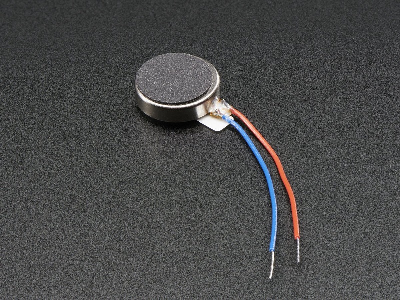
To make a vibration motor vibrate is very simple. All we have to do is add the needed voltage to the 2 terminals. A vibration motor has 2 terminals, usually a red wire and a blue wire. The polarity does not matter for motors.
For our vibration motor, we will be using a vibration motor by Precision Microdrives. This motor has an operating voltage range of 2.5-3.8V to be powered.
So if we connect 3 volts across its terminal, it will vibrate really well, such as shown below: 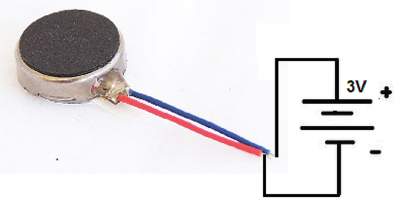
This is all that is needed to make the vibration motor vibrate. The 3 volts can be provided by 2 AA batteries in series.
However, we want to take the vibration motor circuit to a more advanced level and let it be controlled by a microcontroller such as the arduino.
This way, we can have more dynamic control over the vibration motor and can make it vibrate at set intervals if we want or only if a certain event occurs.
We will show how to integrate this motor with an arduino to produce this type of control.
Specifically, in this project, we will build the circuit and program it so that the coin vibrating motor 12mm vibrates every minute.
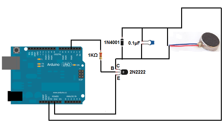
The vibration motor circuit we will build is shown below:
The schematic diagram for this circuit is:
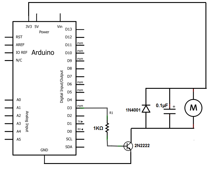
When driving a motor with a microcontroller such as the arduino we have here, it is important to connect a diode reverse biased in parallel to the motor. This is also true when driving it with a motor controller or transistor. The diode acts as a surge protector against voltage spikes that the motor may produce. The windings of the motor notoriously produce voltage spikes as it rotates. Without the diode, these voltages could easily destroy your microcontroller, or motor controller IC or zap out a transistor. When simply powering the vibration motor directly with DC voltage, then no diode is necessary, which is why in the simply circuit we have above, we only use a voltage source.
The 0.1µF capacitor absorbs voltage spikes produced when the brushes, which are contacts connecting electric current to the motor windings, open and close.
The reason we use a transistor (a 2N2222) is because most microcontrollers have relatively weak current outputs, meaning they don't output enough current to drive many different types of electronic devices. To make up for this weak current output, we use a transistor to provide current amplification. This is the purpose of this 2N2222 transistor we are using here. The vibration motor needs about 75mA of current to be driven. The transistor allows this and we can drive the 3v coin type motor 1027. To make sure that too much current does not flow from the output of the transistor, we place a 1KΩ in series with the base of the transistor. This attenuates current to a reasonable amount so that too much current isn't powering the 8mm mini vibrating motor. Remember that transistors usually provide about 100 times the amplification to the base current that enters through. If we don't place a resistor at the base or at the output, too much current can be damaging to the motor. The 1KΩ resistor value isn't precise. Any value can be used up to about 5KΩ or so.
We connect the output that the transistor will drive to the collector of the transistor. This is the motor as well as all components it needs in parallel with it for protection of the electronic circuitry.
Post time: Oct-12-2018


